The Assignment
A CAD and component-selection exercise — not a design showcase
The goal was to redesign a 1930s Peugeot hand-crank coffee grinder using modern off-the-shelf components, verify the design with a fully constrained CAD assembly, and document every component with sourcing and machining requirements — the standard being a design that could actually be built. The interesting part wasn't modeling shapes. It was making every component decision work together under real fabrication and sourcing constraints.
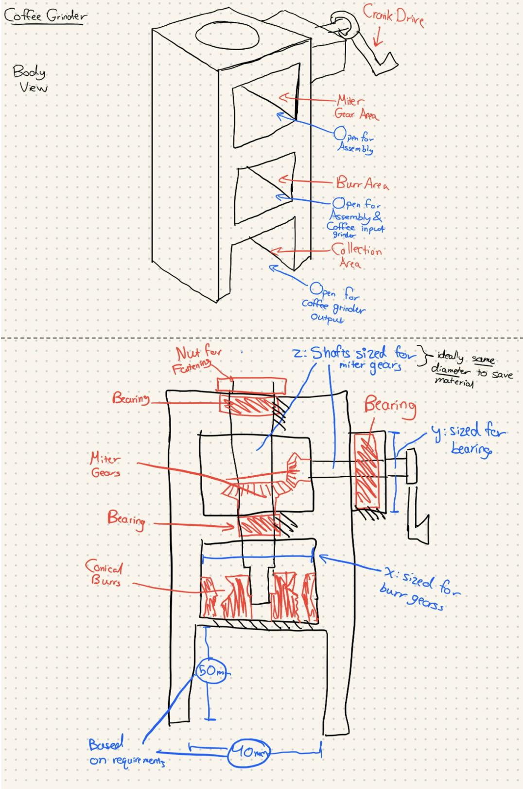
Engineering sketch developed before any CAD — body view (top) with labeled zones (miter gear area / burr area / collection area) and cross-section (bottom) showing shaft sizing logic, bearing placement, and dimension callouts for collection cup clearance
The Engineering Challenge
Making every component decision work together
Three constraints shaped every decision in the project — and each one ruled out the easy path.
Mechanical fastening only
No welding, gluing, or taping — every joint had to be threaded, bored, press-fit, or otherwise mechanically locked. Every connection required a deliberate fastening decision.
At most 3 self-fabricated parts
Everything else had to come from McMaster-Carr with a downloadable CAD file. The constraint forced sourcing decisions first, then design around what's available — not the other way around.
Fully constrained assembly
No part penetrations, nothing falling under gravity, and motion-linked: rotating the crank handle had to actually drive the burrs through the miter gears in the Fusion 360 assembly.
Component Decisions
Five decisions worth explaining
The BOM has eleven component types. Most are straightforward sourcing calls — five required an engineering decision beyond just picking a part.
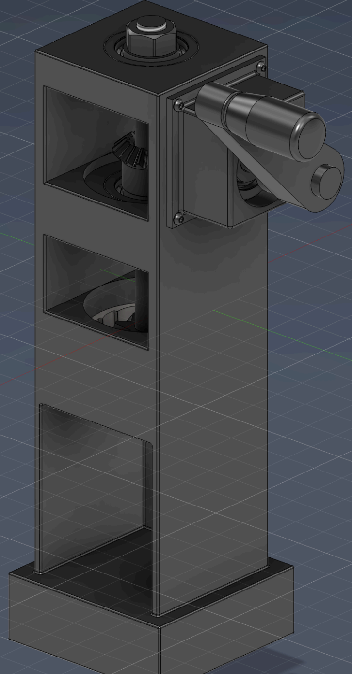
Final CAD assembly — cutaway housing exposes the miter gear area, burr zone, and collection area. Hex nut on top shaft and crank handle on right.
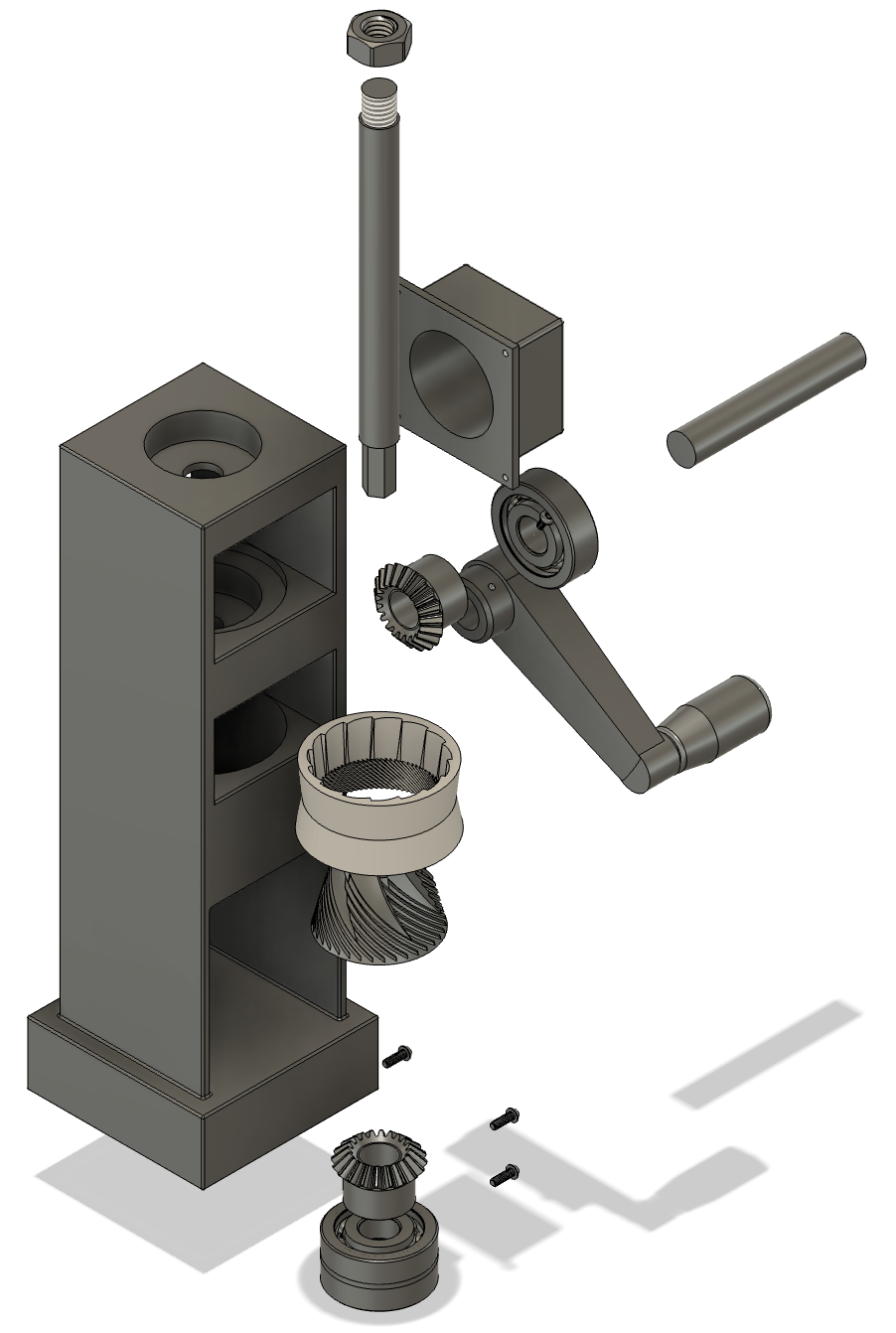
Exploded view showing all 11 component types, sourced from McMaster-Carr and 3D printed, with machining operations including shaft shortening, hex milling, boring, and threading
Main Shaft — McMaster 1265K71
Three machining operations on one off-the-shelf rod
One end hex-milled to key into the miter gear, the other threaded for a locking hex nut — cut, mill, thread on a single stock rod.
Miter Gears — McMaster 2600N1
The axis change — and a bore that needed adjusting
Converts horizontal crank rotation to vertical burr drive through a 90° turn. The stock bore was slightly undersized, so it was bored out to fit rather than sourcing a custom gear.
Crank Handle — McMaster 6547N15
One set screw turns a free-spinning handle into a locked drive input
Bored for a shaft fit, then drilled and tapped for a radial M2 set screw — locking rotation with one fastener instead of reworking the shaft.
Ball Bearings — McMaster 5972K93 (×3)
Standard bearings, 3D-printed housing — tolerance is the design problem
Housed in a 3D-printed mount, one of three allowed self-fabricated parts — bores sized in CAD for a zero-play fit, threads tapped directly into the print.
Conical Burrs — GrabCAD (reverse-engineered)
The one allowed exception — and why it was justified
No shop-machinable or off-the-shelf option existed for the conical grinding geometry, so the burrs were reverse-engineered from a GrabCAD model — the one permitted departure from the McMaster-only sourcing rule.
Assembly
Fully constrained — and motion-linked
The final Fusion 360 assembly is fully constrained: no part penetrations, no components that fall under gravity without a mate, and the motion is live — rotating the crank handle drives the miter gears, which drive the burrs through the vertical shaft. The section view below shows the internal geometry that makes it work: shaft stack, miter gear mesh, bearing seats, and burr alignment, all verified in the assembly before any fabrication would begin.
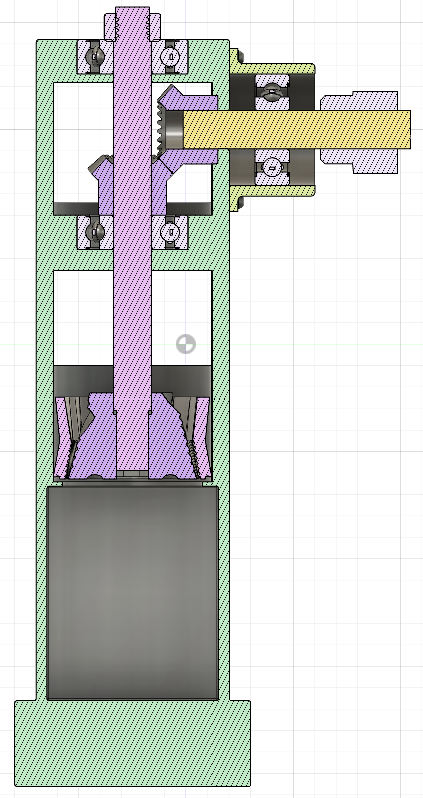
Fully constrained assembly — rotating the crank drives the miter gears, which drive the burrs through the vertical shaft.