The Problem
One bug can cost a 22-ton harvest
Spotted lanternflies — an invasive pest — get swept up in mechanical grape harvesting along with the fruit. Federal regulation rejects entire 22-ton harvest batches if foreign matter exceeds just 0.1%, meaning as few as one or two insects per batch can trigger a full rejection. For New York vineyards already operating on tight margins, that's a significant and unpredictable revenue loss with no reliable mechanical solution on the market.

Filtration sequence — grapes (blue) sink, SLF (white) float, enabling physical separation
The Solution
Rotating tri-sector cylinder — density separation, no power required
The core insight: grapes sink in water, spotted lanternflies float. Our device exploits this density difference using a rotating cylinder with three distinct base sections — solid, fine mesh, and fully open — each serving a different step in the separation sequence. A hand crank drives the rotation, keeping the device fully mechanical, food-safe, and buildable for roughly $140 in materials.
1 — Pour
Harvested grapes enter the cylinder on the mesh base. Juice drains through automatically.
2 — Float-Separate
Crank rotates base to solid section. Water floods in — SLF float to the surface, grapes sink.
3 — Drain
Rotate to mesh section — water drains through, leaving grapes on the base. SLF are skimmed off the surface.
4 — Release
Rotate to open section — clean grapes fall through to collection. Cycle resets.
Design Iteration
Three prototypes, three problems solved
Each version was built to a specific hypothesis, tested against three repeatable mechanical tests — rotation smoothness, water retention time, and max supported weight — then iterated based on what failed.
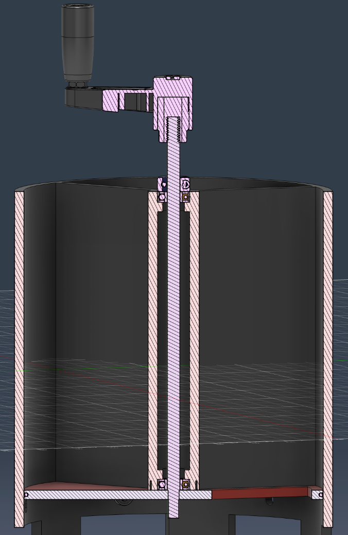
CAD assembly cross-section — shaft, bearing, hex press-fit, tri-sector base, and housing
Prototype 1 — Proof of Concept
Basic tri-base, no sealing
Established that the rotation mechanism worked and the tri-sector concept was physically feasible. The failure was immediate and clear: without any sealing, water drained in seconds.
~10s
Water Retention
2kg
Max Load
Prototype 2 — Sealing Added
O-ring + rubber divider flaps
Added an O-ring around the base perimeter and rubber divider flaps between sectors. Water retention jumped dramatically. The remaining constraint: the base was only press-fit to the shaft, limiting how much weight it could support before deflecting.
52s
Water Retention
2kg
Max Load
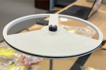
O-ring groove — seals base perimeter against housing
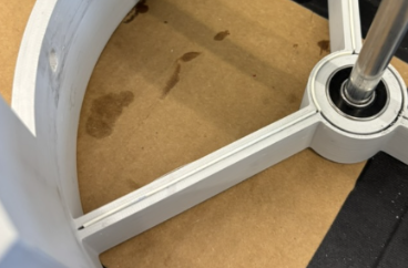
Rubber divider flaps — isolate solid, mesh, and open sectors
Final Prototype — Structural Support
Bearing + shaft collar beneath base
Added a sealed food-safe bearing and shaft collar directly beneath the rotating base. This distributed the load properly and eliminated the deflection issue. Water retention improved further, and max supported weight jumped 4× over earlier versions.
64s
Water Retention
8kg
Max Load
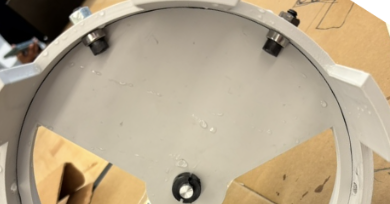
Bearing + shaft collar — distributes load directly beneath the rotating base
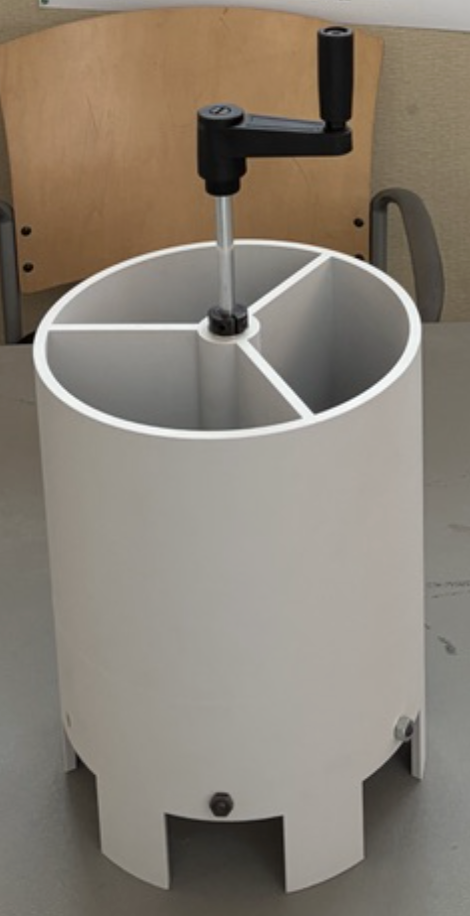
Final prototype — full assembly with bearing support, sealing, and functional rotation
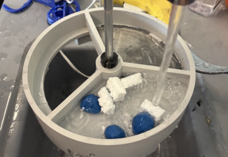
Water retention test — timed seal performance across all three prototype versions
Reflection
What I took away
- The project validated that density-based separation is a genuinely promising approach to a real agricultural problem. The physics work — and the iterative prototyping process of identifying a failure mode, designing a fix, and re-testing was exactly how that gets confirmed.
- Working directly with outside clients — Cornell CALS, Gallo, National Grape — meant the constraints were real: low cost, food-safe, simple enough to use in the field. Designing within those boundaries from day one shaped every decision.
- The jump from P2 to P3 — where adding proper bearing support quadrupled load capacity without touching the sealing system — was a clean lesson in structural isolation: fixing one subsystem can have outsized effects if you've correctly diagnosed where the constraint actually lives.